SECTION 14

Propeller
DESCRIPTION
This section provides general information on propellers - how they function, how they are specified and how they effect boat-and-motor performance. Included is information on test wheels and their use in checking motor operation and procedures for inspecting and repairing damaged propellers.
PROPELLERS
Selection of a propeller with the correct specifications is important to satisfactory operation of any boat and motor combination. The propeller supplied with the motor as it comes from the assembly line, has been chosen for its effectiveness under average conditions of load and speed. For conditions which vary significantly from average, a propeller of different design will be required. A propeller improperly matched to boat and motor combination will fail to provide desired performance, and may cause severe damage to the motor (see Figure 14-1).
In selecting a propeller that will provide the best service, a number of factors must be considered. Among these are the type of boat, motor horsepower available, unloaded weight, normal load and the distribution of the load, speed and pickup requirements and the depth at which the propeller will operate. The most important regulating factors are the design of the hull - this determines how it will ride the water when underway - and the recommended rpm operating range of the motor employed. The ideal propeller selection is one which will permit the motor to operate within its recommended rpm range at full throttle under all load conditions.
 Fig. 14-1. The different thrust requirements of different boats. Boat A- a large runabout; Boat B- a medium runabout, Boat C- a light runabout. Planing hulls require maximum or near maximum thrust to reach a planing attitude. Thereafter power requirements drop off sharply and then, as speed is increased, climb again at a relatively slow rate.
How Does a Propeller Work?
 Fig 14-2 The propeller thrust cone.
A propeller is actually a converter used to change the energy, ar the torque, produced by the crankshaft of the engine ar motor into thrust. This thrust, expressed as push against the water, is what propeis the boat (see Figure 14- 2).
When a propeller turns in the water, it acts somewhat like a screw turning in a block of wood or a bolt turning in a tapped hole. The blades of the propeller pull at the water and attempt to move forward. Water, however, is a liquid, not a motionless solid. Consequently, a part of the propeller's effect is to draw water from before it and discharge it toward the rear, pushing it against the surrounding water and creating what is called a thrust cone. It is the combination of the two actions developed by the propeller's effort to advance that generates the thrust that moves the boat.
Some of the thrust any propeller develops is dissipated into the surrounding water in the form of slippage and turbulence. Propeller slippage and slipstream loss (depending on the type of propeller and its performance characteristics), may be as low as 10% for small, lightly loaded planing hulls; 15% to 20% for average planing runabouts and as great as 40% for large, heavily loaded, displacement boats (large runabouts and heavy cruisers). On barges or heavy workboats, the loss may approach 50%.
 Fig 14-3. Propeller pitch and diameter. Observe how the number of blades on propellers of similar diameter affects total blade area.
Propeller Specifications
Propellers are specified in terms of (1) diameter, (2) pitch, and (3) number of blades. Propeller diameter is equivalent to that of a circle described by the tips of the revolving propeller blades. Pitch is the twist, or angle, at which the blade is set to the direction of travel. Usually given in inches, it is the theoretic distance a propeller will advance in one full turn with no slippage - much as a nut is turned down on the threaded end of a bolt. If slippage were not present, pitch multiplied by the propeller rpm would be the boat speed. The number of blades on a propeller is important only in so far as it determines total blade area. The larger the blade area, the greater the thrust generated by a propeller of a given pitch and diameter. Generally, the load carrying capacity of a propeller is determined by its blade area, with two blades used for high running speed with very light loads, and four blades for low speeds with heavy loads, such as barges or houseboats. Three blade propellers cover the wide range in between and combine good high speed performance with good load carrying ability. (See Flgure 14-3.)
What is an Average Propeller?
Most outboard motors are equipped with a propeller of a certain diameter and pitch that is considered by the manufacturer to be original equipment. This propeller will
 |
| Fig. 14-4. Hull deformations which affect performances. |
allow the engine to run close to its rated rpm at full throttle on an average boat. With the great variety of boat sizes and weights available and the many boat and engine combinations possible, it is obvious that original equipment propeller s are not likely to fit all applications. on many installations the propeller may have to be changed from the original equipment before the first run. The propeller selection charts available with each engine should always be consulted when setting up and outfitting. Because these selection charts are based on average boats with average loads, it may be necessary to make additional changes after the initial test run due to extremes of hull design or load. These conditions, either separately or combined, may cause the engine to run either faster or slower than its rated rpm. This must be corrected by changing the propeller pitch.
Boats of the same general design will often develop widely differing performance characteristics after being in use for a time. How a boat operates can be affected by such matters as water absorbtion (in wood hulls),the presence of marine growth (barnicles, moss, etc.) on hulls of all materials, hull deformations resulting from improper storage or handling (se e Figure 14-4), or even such a simple thing as an excess of water in the bilges. Redesign of deck house, or cabin facilities or changes in hull configuration by transom extensions, etc., can significantly alter the way in which a boat behaves when underway. Complaints of faulty motor performance have often been traced to changes made to the boat. When alterations have been extensive, failure to change the motor and propeller to accommodate new operating conditions can seriously affect overall performance.
Propeller Matching
The two factors of pitch and blade area work in combination to determine the amount of thrust generated by the motor. Pitch and blade area also determine the amount of power required to turn the propeller. The larger the propeller and steeper the pitch, the more power needed to turn the propeller at an effective speed. Since the load applied to the engine is largely determined by pitch and blade area and since the engine, in order to operate efficiently, must develop an rpm within its operating range when running at fun throttle, it is obvious that propeller pitch and blade area must be selected to accommodate the maximum of engine capacity (see Figure 14-5 and 14-6).

Fig. 14-5. Low pitch. |

Fig. 14-6. High pitch. |
If the propeller is too small or the pitch too shallow, the load on the engine will be insufficient and the rpm will exceed the critical range and overspeed; if the propeller is oversized or the pitch too great, the engine will be overloaded and the rpm will never reach the lower limits of the operating range. Maintained for any length of time, either overspeeding or overloading, will materially shorten a motor's service life.
Each model and type of motor has its own rpm operating range. In the principles of operation section of this manual, the mechanical conditions that determine the range are explained. The range specific to each motor is noted in the Operator's Manual furnished with each motor and on the motor specification sheet in Section 2 of this manual. (See Figure 14-7.)

Fig.14-7. Brake horsepower chart showing comparative ratings of two outboard motors.
A careful determination of the use for which the boat and motor is intended is important in making a correct propeller selection. Where speed is important, pitch is usually given first consideration as when selecting a propeller for the light planing type hull. Blade area is of greater importance when choosing the wheel for heavier planing or displacement hulls such as are used in large runabouts, cruisers, heavy water ski rigs, and the like. The two elements must be considered together, however, neither may be emphasized to the exclusion of the other.
Regardless of size, all outboard motors are designed to run with full throttle at the rated rpm or slightly above. This not only provides the best performance but has a direct bearing on engine life and fuel economy. Propeller selections should be made with this in mind. A correctly selected propeller will provide adequate performance throughout the entire speed range of the engine. The best test of propeller selection is a trial run with a tachometer.
Under trial conditions the following rule of thumb may be observed:
IF THE FULL-THROTTLE TACHOMETER READING IS BELOW THE RECOMMENDED OPERATING RANGE OF THE RPM, A PROPELLER OF LESS PITCH IS INDICATED. IF THE FULL-THROTTLE TACHOMETER READING IS ABOVE THE RECOMMENDED OPERATING RANGE, A PROPELLER OF GREATER PITCH IS INDICATED.
Installation
Proper installation of the motor is essential to satisfactory performance. A motor set at an incorrect tilt angle will affect both how the boat rides the water and how it steers. Proper transom height and condition of keel are equally important (see Figure 14-8).

Fig. 14-8. Installation details.
Each new V-4 motor is supplied with a template which can be used in mounting the engine. However, a more accurate mounting can be made through the use of a special drill jig available as a special tool.

Fig. 14-9.Mesuring transom height. |
Most boats manufactured for use with outboard motors have transoms properly designed to accommodate correct installation. To operate at best advantage, a motor must be installed at the correct height. If the transom is too high, propeller slippage (cavitation) will result. Cavitation is a condition in which the propeller runs wild in a pocket of air. Little power is produced and there is danger of overspeeding and improper cooling of the engine. Too low a transom will produce drag, resulting in loss of speed and creating an undesirable spray. Motors are made to accommodate 15 or 20 inch transoms, measured on a line perpendicular to the planing surface. For average family use, a good rule is to run the anti-cavitation plate about 1 to 1-1/2 inch below the bottom of the boat at the transom centerline (see Figure 14-9).
Keel interference, developed by too wide or deep a keel, is a frequent cause of cavitation. A deep, square-ended keel will permit air bubbles to flow back to the propeller, thus affecting propeller performance. To correct this condition, tapering or reshaping the keel is sometimes necessary. The aft end of the keel should be tapered to approximately 1/4 inch in height at the transom. The taper should begin at least 30 inches forward of the end of the keel.
To obtain maximum performance, the engine should be adjusted to allow for variation in the angle formed by the transom and the bottom of the boat. Since this angle will vary with individual boat design, all motors are provided with tilt adjustment which should be checked at the time of installation.
In the normal operating position, the tilt angle should be adjusted so that the driveshaft is perpendicular to the water when the boat is moving at top speed. If the engine is tilted in too close to the transom, the bow will dig or plow in the water, causing excessive steering torque and poor performance. The boat will have a tendency to swerve to the left and steer very hard to the right. If the engine is tilted too far out from the transom, the boat will gallop or porpoise and steering will be equally difficult. The boat will behave skittishly tending to swerve to the right and steer hard to the left. The best performance tilt angle varies according to hull design. Planing boats ride with only 30 to 40% of the length of the boat actually in contact with the water. Observation at water level of a planing boat in operation ought to reveal a definite tilt up at the bow. Displacement, (non-planing) boats ride on a more or less level keel and tilt up at the bow is negligible. (See Figures 14-10 and 14-11.)

Fig. 14-10. The effect of motor tilt angle on performance.

Fig. 14-11. The effect of motor tilt angle on steering.
 |
Fig. 14-12
Typical test tachometer |
TEST WHEELS
Final testing and tuning of any outboard motor is best performed under actual conditions - on a boat in open water where all conditions of normal operation may be observed. Where this is neither possible nor convenient, test wheels may be used. All tests, whether on open water, at dockside or in shop tanks, should include provision for an accurate determination of crankshaft rpm while the motor is running at full throttle. Attempting to check out or tune a motor labouring at low rpm in the shop test tank or at dockside with a regular propeller is futile. Rpm must be "up" if all required adjustments are to be made correctly. This particularly applies to adjusting the slow and high speed carburetor needle settings. Accurate test tachometers may be obtained from the Fox Valley Instrument Co., Cheboygan, Michigan. The model shown in the accompanying illustration (Figure 14-12) is a Fox Valley Model 200 Universal Tachometer.
The use of test wheels need not be confined to shop test tanks. Under certain conditions it may be advantageous to check motor performance at dockside without removing the motor from the boat. Dockside testing provides an opportunity for final adjusting and tuning of the engine under close to actual operating conditions, and an opportunity to check remote control adjustments, over all rigging and electric harness/junction box installations.
For dockside testing, the boat should be firmly anchored, with ample water around and below the propeller. The test procedure is simple: - Remove the propeller to install the test wheel;
- attach the tachometer leads;
- start and run motor to observe performance characteristics and
- check these against the established rpm operating range for the specific model. (See Figure 14-13.)
 |
Fig. 14-13
Typical test tachometer |
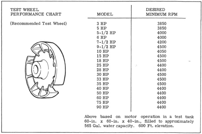
Each of the available propeller test wheels has been designed and calibrated for a specific model or horsepower simulating thrust and load conditions encountered during normal operation.
A test wheel performance chart appears below. On this chart, the desired minimum rpm shown for each model has teen calculated for test running in a tank 60 inches x 60 inches x 40 inches filled with approximately 565 gallons of water and installed at 600 feet above sea level. When testing under other conditions the following should be taken into account:
- The type and size of test tank and the turbulence created by the test wheel.
- The effect of exhaust gases from the tank on the engine being tested.
- Elevation above sea level.
- Atmospheric conditions at time of testing.
It should be observed that any internal combustion engine develops its maximum horsepower at sea level where the air taken in with fuel vapour is most dense. Developed horsepower is reduced by approximately 3% for each 1000 feet of elevation up to 8000 feet. Using the chart as a guide, local approximations for acceptable performance (rpm) are not too difficult to determine. By recording performance of several of each motor model, averages may be calculated.
 |
| Fig. 14-14. A propeller damaged by striking a underwater obstacle |
 |
| Fig. 14-15. A propeller with minor surface deformations can be repaired. |
Constantly changing atmospheric conditions (barometric pressure and humidity) also affect engine performance. To a miner degree, rpm increases with a high barometer - and decreases with a lower pressure. Variations of as much as 100 to 150 rpm may be noted as a result of changing atmospheric conditions.
Propeller Care
A bent or nicked propeller will set up vibrations in the motor, which may have a damaging effect on the other operating parts. There will be a definite loss of power and efficiency with a damaged propeller. An off-pitch propeller quickly reveals itself with motor performance symptoms ordinarily associated with faulty ignition or carburetion - rough or ragged running throughout the intermediate speed ranges and increasing roughness and vibration at top or near top speeds.
Three conditions affecting propeller performance:
- Severe damage to, or loss of, portions of the blade surface (see Figure 14-14).
- Miner deformations of blade surface (see Figure 14-15).
- Malfunction of the propeller shock absorber hub.
Severe Damage
Severely damaged propellers are almost impossible to repair and should be discarded.
A propeller that has lost any portion of one or more of its blades which has suffered appreciable distortion will almost certainly be off balance. Continued use of an off-balance propeller will cause vibration damage to the engine or boat. A badly damaged propeller should be replaced at once.
Minor Damage or Deformation
Propellers that have suffered only miner nicks or distortion usually can be repaired satisfactorily. Minor nicks may be filed smooth. Surface distortions, which are sometimes difficult to detect, should be corrected. Where distortion is suspected, the propeller should be removed from the shaft and checked on a propeller straightening fixture. A fixture is made for each size and pitch propeller.
General Procedure for Straightening Propel
 |
| Fig. 14-16. Use light blows with a soft mallet on high areas of the blade. A leather pad placed under low areas of the blade will help to correct very small deformations. |
- Remove propeller from start and place on correct straightening fixture (se e above). Make sure propeller hub seats at base of the fixture spindle and that the leading edge rests firmly against the stop provided. Use adapters or bushings where these have been furnished with the fixture (see Figure 14-16).
- Inspect the propeller carefully. Off-pitch surfaces will not conform to the fixture surfaces.
- Place a 1/8 inch thick leather pad under the low areas of the blade and strike the blade very carefully at the high point (see Figure 14-16). Use a rawhide mallet.
- Check all blades of the propeller and straighten as required.
- Check the shock absorber hub and propeller shaft. Replace propeller if hub wear or damage is apparent. Replace shaft if bent, damaged, or misaligned. (The shaft may be checked by rotating it by band. NOTE: Spark plugs should be removed before turning propeller shaft both to reduce the effort required to overcome compression on non-gearshift models and to prevent accidental starting.)
- Reassemble propeller to shaft using new cotter pin.
Malfunction of the Propeller Shock Absorber Hub
Propellers are assembled with a precision fit rubber bushing pressed inside the propeller hub that provides a friction engagement between the propeller and hub. This bushing effects a connection that is firm enough to allow normal operation, yet permits the propeller to slip if it strikes an underwater obstacle. Older models employed a shear pin. Once broken, however, the shear pin permitted the shaft to rotate freely without turning the propeller. Driving power was interrupted and could not be restored until the pin was replaced. The shock absorber hub eliminates this difficulty.
 |
| Fig. 14-17. Checking slip clutch torque. |
With the shock absorber, power interruption is only momentary; when the propeller strikes an obstacle and is suddenly halted or slowed, the shaft and hub continues to turn inside the propeller. When the propeller breaks free, full hub engagement is immediately restored. Unless the propeller is very severely damaged, the boat can still be manoeuvred to where inspection or repairs can be made.
For proper shock absorber action the rubber bushing must be sufficiently tight inside the propeller so that torque required to make it slip is greater than that required to turn the propeller in normal operation. A special fixture has been designed to permit testing for required torque limits (see Figure 14-17). Correct hub torque values for each motor are shown in the torque charts (see Overhaul, Section 5, this manual).